ROTOR BALANCING
Rotor Balancing is a type of analysis that compares the vibration profile with the rotation of a mechanical element to characterize inconsistent weight distribution around the diameter while calculating the amount and position of the weight necessary to offset the net imbalance.
Rotating elements of a system are a common source of unwanted vibration. Any mass that is not rotating around its center of mass will produce vibration. An everyday example of this would be car tires. Within every tire, small changes in density and thickness of the rubber cause one section to be heavier than the rest of the tire. This means that as the tire spins, that section will pull more than the rest, creating an imbalance.
This imbalance in the tire is offset with the addition of weights directly opposite this heavy spot. With the weight of the tire more uniformly distributed around the diameter, the vibration decreases and the car will run more smoothly.
The same general concept is used for industrial machinery. The main difference is the accuracy to which the weight is distributed and the types of rotating objects it is applied to. Rotating machinery is a common element of any facility. Motors drive fans, gear boxes, rollers, and many other types of mechanical systems.
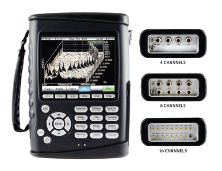
Until recently, rotor balancing was a process that required a trained engineer. The process involved taking baseline measurements, graphically plotting on polar graphs, and calculating influence coefficients. Using Crystal Instruments’ handheld CoCo dynamic signal analyzer, the process has been largely automated. An operator can now perform a balancing operation simply and quickly using an automated process that instructs when and how to make changes to the system.
One Plane Rotor Balancing
The Rotor Balancing application is available in both operation modes of the CoCo: the Dynamic Signal Analyzer (DSA) Mode and vibration data collector (VDC) Mode. This means the rotor balancing application runs as a standalone operation or as part of a routine maintenance program.
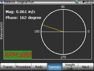
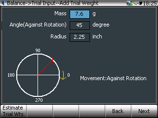
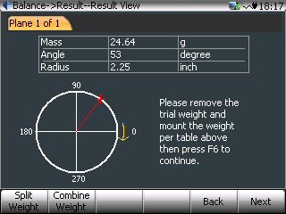
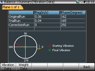
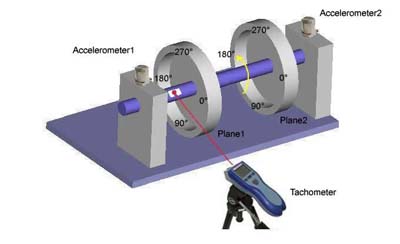
The balancing procedure consists of four steps. The first is to acquire a baseline vibration level. This characterizes the magnitude and direction of the vibration as the system is currently configured. Next, a known weight is added to a known location along the edge of the rotor. The rotor is spun again and a new reading is taken. The CoCo will use these two readings to calculate the influence coefficients and the weight required to offset the balance in the baseline reading. The known weight will be removed, and the correction weight will be added to the motor. A final spin-up of the rotor verifies that the vibration has decreased. The process can be repeated to further reduce the imbalance and vibration.