MODAL TESTING
Modal testing is a common method of characterizing the vibrations of a structure by imparting a known force and measuring the response of the structure. By measuring both the input to the structure and the response, the frequency response of the structure can be calculated. Calculating the frequency response over multiple locations, either simultaneously or individually, will yield data that can be used to estimate the dynamic response of the structure.
The scale of a modal test can vary greatly. Test structures can be as small as silicon wafers used in electronics, and as large as multistory industrial sifters used at rock quarries. The size and geometry of the test structure will play a role is choosing how to excite it. The two most common methods are impact testing using a modal hammer and shaker testing.
After collection, the data can be processed using ME’scope, a popular modal analysis software from Vibrant Technologies. The result of the measurements and processing would be an animated model of the operating deflection shapes (ODS) that clearly illustrates the movement of the structure. Most commonly, these models are analyzed to identify modal frequencies.
At these frequencies the structure vibrates with minimal input energy. Exciting the structure at these frequencies can easily cause damage to the system. Characterizing the response of the structure mean that the design can be changed to reduce the response, or the operating conditions can be adjusted to avoid failures.
(For step-by-step instructions on how to conduct modal testing on the CoCo instruments, click here to download the CoCo Modal Data Acquisition Operation Manual.)
Impact Hammer Modal Testing
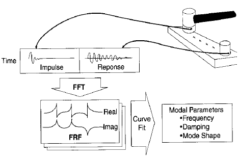
A typical impact test will use an impact modal hammer and a response accelerometer. It is important to consider the scale of the test structure when selecting these sensors. The impact hammer imparts an impulse force into the system and is intended to excite a broad bandwidth. The Impact hammers range in size, sensitivity, and hardness depending on the scale of the system they need to excite and the bandwidth of interest. Similarly, the response accelerometer needs to be sensitive enough to detect the ringing of the structure without saturating. The output of the impact hammer and accelerometer are used to calculate the frequency response functions (FRFs) across the structure.
It is usually easier to mount the accelerometer in a single location and vary the impact location. This type of test is referred to as a ‘roving impact’ modal test. It is important to carefully plan and document the impact locations for the test. This information is crucial when piecing together the individual FRFs to analyze the response of the structure as a whole. Third party software packages, such as Vibrant Technology’s ME’scope, can use the FRF and location data to animate a computer model. These animations help to clearly visualize the operating deflection shapes (ODSs) of the structure.
Figure 1: Illustration of a typical impact hammer modal test and signal processing
The following equipment is required to perform an impact hammer modal test:
- An impact hammer to excite the structure. With the CoCo we recommend using an IEPE impact hammer, which allows the hammer to be connected directly to the analyzer without extra signal conditioning.
- One or multiple accelerometers that are fixed on the structure. Again, IEPE accelerometers can be used directly with CoCo without additional signal conditioning.
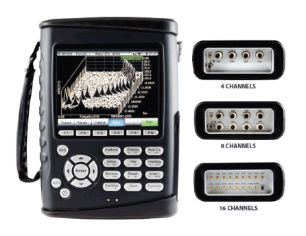
- Coco-80 or CoCo-90 dynamic signal analyzer
- The CoCo can be used to extract the resonance frequencies and damping characteristics of the structure. In addition third party software can be used to extract modal shapes and animate the operating deflection shapes.
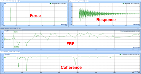
A wide variety of structures and machines can be subjected to impact hammer modal testing. Of course, different sized hammers are required to provide the appropriate impact force, depending on the size of the structure; small hammers for small structures, large hammers for large structures. Realistic signals from a typical impact test are shown in Figure 10.
Impact Test Analyzer Settings for Modal Testing
The following settings are used for impact hammer modal testing.
- Trigger Setup including trigger level and pre-trigger are used to capture the transient signal for FRF processing. It is important to capture the complete impact and response signals in the block (or frame) of the FFT analyzer. To insure that the entire signal is captured, the analyzer must be able to capture the impulse and impulse response signals prior to the occurrence of the impulse with the pre-trigger.
- Force-Exponential Window: Selecting the correct window function is critical for ensuring accurate measurements. The FFT process requires that the impact and response signals be completely contained within a single block to prevent abrupt changes at the beginning and end. These abrupt changes in the time domain signal correspond to high-frequency data in the FFT. The impact is an impulse event of very short duration that is easily captured in a single block; however the response can ring depending on the stiffness and damping of the structure.
- Impact modal testing should be done using the Force-Exponential window type. In this window, the data in the first part of the block (frame) is left untouched. The impact will fall completely within this section, as well as the initial response of the structure. In the second part of the block, an exponential window is applied to force any ringing in the response to zero by the end of the block. This minimizes erroneous high-frequency content in the FRF.
- Accept/Reject: Because accurate impact testing results depend on the skill of the operator, FRF measurements should be made with averaging, a standard capability in all modern FFT analyzers. FRFs should be measured using at least 4 impacts per measurement location. Since one or two of the impacts during the measurement process may be bad hits (too hard causing saturation, too soft causing poor coherence or a double hit causing distortion in the spectrum), an FFT analyzer designed for impact testing should have the ability to accept or reject the result of each impact after inspecting the impact signals. An accept/reject capability saves a lot of time during impact testing since you don’t have to redo all measurements in the averaging process after one bad hit.
- Modal Damping Estimation. The width of the resonance peak is a measure of modal damping. The resonance peak width should also be the same for all FRF measurements, meaning that modal damping is the same in every FRF measurement. A good analyzer should provide an accurate damping factor estimate. CoCo uses a curve fitting algorithm to estimate the damping factor. The algorithm reduces the inaccuracy caused by the poor spectrum resolution or noise.
- Modal Frequency estimation. The analyzer must provide capability of estimating the resonance frequencies. The CoCo uses an algorithm to identify the resonance frequencies based on the FRF.
Recommended for Modal Testing
The CoCo-80 (and CoCo-90) dynamic signal analyzer and vibration data collector are recommended by Crystal Instruments for Modal Testing. The CoCo series feature an intuitive interface, 2 to 16 channel configurations, and excellent product support to guide users through all their testing needs, including modal testing.